KISTERSオートメーションサーバー(KAS)
ユーザーとの対話なしに自動変換を実現するバッチツール
繰り返される手順をオートメーション化する場合、KISTERSオートメーションサーバー KASを3DViewStationシリーズの全製品と組み合わせてご利用いただけます。このとき大概、ネイティブ3D CADデータ形式からより容量の小さい3DVSデータ形式への変換が行われます。こうすることにより、例えばネイティブ形式では読み込みに5分もかかる5 GBのCatiaアセンブリーを3DVS形式への変換後、わずか1秒で読み込めるようになります。その際、情報がすべて失われないように設定したり、情報量の削減も可能。変換ではモノリシック、または「ばらばらの状態」を選択でき、その場合はジオメトリファイルごとにひとつに3DVSファイルに変換されます。こうすることで、複数取り付けの可能性のある部品が変更されたとしても、変換の手間を大幅に削減できます。また、KASではそれだけでなく、PLMシステムの自動画像プレビュー作成、作成したアセンブリー関連ビュー全体の3D/2D形式でのエクスポート、アセンブリー全体のデフォルト3D形式でのエクスポートも可能です。
アドバイスさせていただきます。
技術
+49 2408 9385 517
以下のプロジェクト例は、KASバッチツールのお客様のものです。
あるヘリコプターメーカーでは、可視化前に社内のCADネイティブデータをすべて3DVS形式に変換。おかげで、非常に短時間でヘリコプターの可視化が可能となっています。モノリシックの場合、2~300万の部品の読み込みにかかる時間は10秒未満。CADシステムでは、ヘリコプター全体を読み込むなど到底不可能でした。
とあるトラックメーカーでは、KASにより、社内のCADネイティブデータをバッチ処理でより容量の小さい3DVS形式に変換しています。特定のファイルはメタデータから制御され、さらにBREP内で変更されます。トラックが設定された後、KASを介して部分的に疎外されたSTEPデータに変換され、2D図面が自動的に生成されます。
プラントエンジニアリング会社がKASを使って約5TB(!)CADデータを3DVS形式に変換します。おかげで、約2億個の部品から成るプラントでも、簡単に3DViewStation WebViewerへの読み込みが可能。
とある造船所では、船全体を3DVS形式に変換するためにKASが使用されています。この変換を行うことにより、約1000万個の部品を約15秒でVR版、さらにはデスクトップ版、WebViewer版にも読み込めるようになります。
当社のコラボレーションソリューション: VisShareでは、ネイティブデータの3DVS形式への変換と画像プレビューの作成のため、バックグラウンドでKASが使用されています。
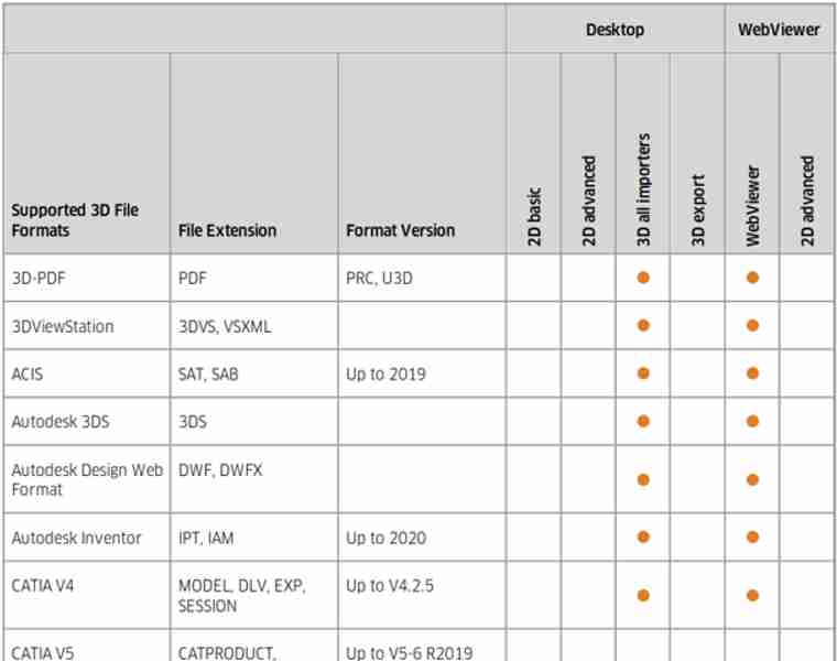
3Dデータフォーマットのサポート
出て行け:
ネイティブ&ニュートラルなCADデータの3Dインポート。
Catia, NX, Creo, Solidworks, SolidEdge, Inventor, SAT, Parasolid, JT, STEP, 3D PDF, Revit, GLTF, 3DXML, VRML...
3Dエクスポート:
STEP, JT, 3D PDF, 3MF, Parasolid, VRML...
2Dデータフォーマットのサポート
Excerpt:
2Dインポート - 図面、Office、画像:
Catia CatDrawing, NX 2D, Creo DRW, Solidworks slddrw, DWG, DXF, HPGL, 2D PDF, TIFF, JPEG...
2Dエクスポート:
DXF, PDF, CGM, PNG, SVG, BMP...
The interacive Kisters 3DViewStation and also batchtool KAS are no classic CAD converters, but can help translating 3D file formats into others and also allow to derive high quality 2D vector or raster drawing and images from the 3D-models.
Translating into a light weight representation like the Kisters 3DVS file format opens new options for 3D-based technical documentation, 3D technical illustrations, 3D assembly instructions, manufacturing, design review, collaboration and more. By staying in the 3D world, processes will become streamlined, the quality of the assets will be increased and a lot of interaction time will be saved.
With thousands of companies using of software we learned, that in many cases like collaboration a translation into a neutral file format could be avoided, if a Web based visualization solution like our 3DViewStation WebViewer version was used.

What do I need to know when translating a 3D-CAD model into another neutral 3D file format?
We think, that there are several important considerations to keep in mind, like file format selection, model structure, views, annotations, metadata and more:
So first of all, we need to choose an appropriate neutral 3D file format for the translation. The most important neutral BREP file format for sure is STEP (Standard for the Exchange of Product Data). Here typically AP 214 and AP 242 are used. In the automotive industry JT has become an important standard. Less important, but still used is IGES (Initial Graphics Exchange Specification). Finally there are several rather simple tessellation based file formats like STL (Standard Tessellation Language), VRML (Virtual Reality Modelling Language) and OBJ, see also our complete file format list, section export 3D. The specific format you choose will depend on the requirements of the receiving software or system. BREP based file formats are intended to exchange between CAD systems, while tessellation based file formats are good for many visualization needs.
In most cases we need to take into account the structure and hierarchy of the original CAD model and how it will be translated into the neutral file format. CAD models often have an organized structure with components, assemblies, and sub-assemblies. Ensure that the translation process maintains this structure for better organization and future editing or manipulation. Be aware, that some file formats do not support the structure and hierarchy.
Many 3D-CAD systems support so called captures or PMI views, which are all called views in the 3DViewStation world. As not all file formats support such views, you we might have to select the right one, if we need to retain them.
If your enterprise follows the MBD concept (Model Based Definition, also called 3D Master), then you replaced 2D drawings by 3D annotated models. Translating such files requires a target file format, which will support PMIs (Product Manufacturing information). STEP AP 242 and JT are such file formats. When using Kisters 3DViewStation or KAS in order to translate these files, you need to ensure, that the correct import and export settings have been set.
Today it is very important to preserve metadata, attributes, and properties associated with the CAD model, such as material information, part numbers, or custom properties during the translation process. Be careful: Some formats may support metadata transfer, while others may require additional steps or custom scripting, some file formats might not even support any.
We, the visualization experts, are aware of how visual properties, such as colors, textures, or surface finishes, will be handled in the translation process. Some neutral file formats may support these visual attributes, while others may require additional steps or settings to preserve or recreate the desired appearance in the target application.
We also need to understand the level of geometry accuracy and detail required for the translation. Different file formats may handle geometry representations differently, such as using NURBS (Non-Uniform Rational B-Splines) or polygonal mesh representations. Consider the level of precision and detail needed for your intended application and ensure the chosen file format supports it.
We need to confirm that the units and scale of the original CAD model are correctly preserved during the translation. This is crucial to ensure dimensional accuracy and proper scaling in the resulting neutral file format. Verify that the translated model aligns with the intended unit system and scale in the target application.
In case we know the target system we do have a chance to understand the compatibility and limitations of the target software or system with the chosen neutral file format. Different software packages or systems may have varying support or interpretation of specific file formats. Ensure that the target application can correctly read and interpret the translated file for optimal compatibility and usability. We can help selecting the most promising file format depending on the target system.
While KAS allows to translate file in batch mode, you can use 3DViewStation Desktop or WebViewer version to do these translations manually. But they are also good to review the translated model to confirm its accuracy and integrity. Check for any errors, missing geometry, or unexpected changes that may have occurred during the translation process. There are also quality checkers available on the market, which might be used before forwarding the file or before importing them into the target system.
When talking about 2D exports, first of all we should mention, that it is no trivial task to derive a full scale, high quality, still small 2D vector representation for a 3D CAD model. At the same time generating an image, like a thumbnail preview of even a high resolution image is rather easy.

Why does someone want to export a 3D-CAD model to a 2D vector drawing?
There are several reasons why someone may want to export a 3D CAD model to a 2D vector drawing:
Many manufacturing processes still rely on 2D representations, especially for certain types of fabrication, such as laser cutting, CNC machining, or sheet metal bending. Exporting a 3D CAD model to a 2D vector drawing allows manufacturers to generate the necessary cutting or machining paths, specify part dimensions, and determine material requirements.
In some industries, older software or equipment may only support 2D vector formats. Exporting a 3D CAD model to a 2D vector drawing allows compatibility with such systems, enabling data exchange or integration with existing workflows without the need for complex conversions or software upgrades.
In certain contexts 2D vector drawings can be useful for visualizing a design. For example, in architectural or interior design, 2D floor plans or elevations provide a comprehensive view of the space, including the layout, dimensions, and other architectural details. These drawings are often easier to understand and work with for certain design-related tasks.
2D vector drawings are commonly used for documentation purposes. They provide a clear and detailed representation of the design, including dimensions, annotations, and other important information. These drawings can be shared with stakeholders, such as manufacturers, contractors, or clients, for better understanding and communication.
Today 2D vector drawings are often used for 2D technical illustrations, 2D assembly instructions, or 2D user manuals, mostly provided as 2D PDF file or printed documents. By exporting a simplified 2D representation of a 3D CAD model, complex designs can be visually broken down into clear, step-by-step instructions, aiding in the assembly, maintenance, or operation of a product or system.
In some cases, a 2D vector drawing may be preferred for design review or collaboration purposes. By simplifying the representation to 2D, it becomes easier to focus on specific aspects of the design, such as individual components, dimensions, or structural details, without the complexity of the 3D environment. This can facilitate discussions, feedback, and design iteration.
By exporting a 3D CAD model to a 2D vector drawing, individuals can leverage the benefits of both formats, combining the rich detail and accuracy of the 3D model with the clarity, simplicity, and compatibility of the 2D vector representation for various applications.

What do I need to know when exporting from a 3D-CAD model to a 2D vector file?
Determining the appropriate file format for the vector file is key. In the manufacturing industry common file formats used for 2D drawings include 2D DXF (Drawing Exchange Format), 2D PDF (Portable Document Format) and SVG (Scalable Vector Graphics). Sometimes the file format required depends on the target application and system, where it will be used.
Organize your CAD model into appropriate layers and/or blocks before exporting. This allows for better control over different components, annotations, or visual elements in the vector file. 3DViewStation APIs and our batch tool KAS allow to automatically build layers and blocks, based on the product structure of the 3D-CAD model.
Familiarize yourself with the export settings and APIs provided by 3DViewStation and KAS. These settings may include options for curve smoothing, resolution, and compatibility with different software or devices. Decide whether you want to include hidden lines in the exported vector file or show only visible lines. Depending on the purpose of the 2D representation, you may need to enable or disable hidden line removal to accurately represent the design.
3DViewStation and KAS can help you simplifying or optimizing the geometry of your 3D CAD model before exporting to a 2D vector file. They allow to remove unnecessary details, such as internal components or hidden features, to keep the resulting vector file clean and lightweight. This can help improve performance and reduce file size.
Consider the desired level of quality and precision in the exported vector file. This relates to the smoothness of curves, accuracy of angles, and overall detail. Higher quality settings may result in larger file sizes, so balance your requirements with file size considerations. Very often it is crucial to keep file size as small as possible, which requires intelligent vectorization and compression algorithms, like 3DViewStatoin and KAS provide.
We need to ensure that the dimensions of your 3D model are accurately translated to the 2D vector file. Check the scaling and units of measurement to avoid any discrepancies. File formats like PDF know their paper size, which might make it easier to retain the intended scale during the conversion.
Leveraging 3DViewStation Desktop or WebViewer version you can verify that the exported vector file represents the desired geometry and level of detail. Pay attention to curves, arcs, and splines, as they may require higher resolution or special settings to maintain smoothness.
Some file formats do support line thickness and styles. As 3D CAD model do not have any settings like that, we’ll need to specify them in such a case. Different software may handle linework differently, so be prepared to adjust these settings during the export process.
3DViewStation and KAS will care for colors and fills automatically, depending on black & white or color setting: You can assign specific colors to different layers or components, interactively or via API or opt for a monochromatic representation during export.
Finally, if your 3D CAD model includes 3D annotations, labels, dimensions, balloons, tables or text blocks, verify that they are appropriately exported and legible in the 2D vector file. These annotations are essential for conveying important information about the design and can aid in manufacturing or construction processes.