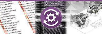
Kisters Automation Server (KAS)
Herramienta de lotes para la conversión automatizada sin interacción del usuario
El Servidor de Automatización KAS de Kisters es el complemento ideal para toda la línea de productos 3DViewStation cuando se trata de automatizar procedimientos repetitivos. Se trata sobre todo de la conversión de datos nativos de CAD 3D en el formato de datos de poco peso 3DVS. Por ejemplo, un componente Catia de 5 GB, que tarda 5 minutos en cargarse en el modo de carga nativo, puede cargarse en solo 1 segundo después de su conversión al formato 3DVS. De este modo, se recibe toda la información y, dependiendo de los ajustes, también puede reducirse. La conversión puede ser monolítica o "totalmente fragmentada" es decir, se convierte un archivo 3DVS por cada archivo de geometría. Esto reduce considerablemente el esfuerzo de conversión después de la modificación de una sola pieza que puede ser utilizada varias veces. El KAS también se utiliza a menudo para generar automáticamente imágenes de vista previa para los sistemas PLM. O para exportar todas las vistas que se hayan creado en componente de formato 3D o 2D o para exportar el componente total en un formato 3D estándar.
Póngase en contacto con nosotros ahora - estaremos encantados de asesorarle
Estaremos encantados de asesorarle
Ventas
+49 2408 9385 517
Los siguientes ejemplos de proyectos provienen de nuestros clientes de la herramienta de lotes KAS:
Un fabricante de helicópteros convierte todos sus datos CAD nativos en el formato 3DVS antes de la visualización. La visualización del helicóptero configurado es, por lo tanto, sumamente acelerada. Como un monolito, el tiempo de carga es inferior a 10 segundos en 2-3 millones de piezas. El sistema CAD nunca consiguió cargar el helicóptero completo.
Un fabricante de camiones utiliza el KAS para convertir sus datos CAD nativos en lotes al formato ligero 3DVS. Ciertos archivos están controlados por metadatos, y también se manipulan en BREP. Después de que el camión ha sido configurado, se convierte en datos STEP parcialmente manipulados en KAS de acuerdo con los requisitos del cliente, se generan planos 2D automáticamente.
Una empresa de ingeniería de plantas utiliza KAS para reducir aprox. 5 TB (!) Convertir datos CAD al formato 3DVS. Así es capaz de cargar una planta con aproximadamente 200 millones de componentes con WebViewer de 3DViewStation.
Un astillero utiliza KAS para convertir una nave completa al formato 3DVS. El tiempo de carga posterior de aprox. 10 millones de componentes es de unos 15 segundos en la edición VR, pero también en la versión de escritorio y WebViewer.
Nuestra solución de colaboración: VisShare utiliza KAS en segundo plano para convertir los datos nativos en el formato 3DVS y generar imágenes de previsualización.
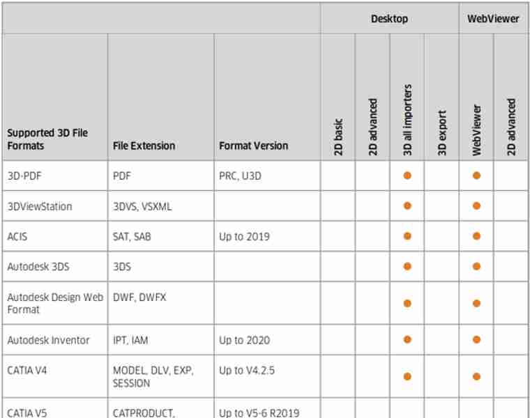
Formatos de datos 2D compatibles
Resumen:
Importación 2D de planos, Office, imágenes:
Catia CatDrawing, NX 2D, Creo DRW, Solidworks slddrw, DWG, DXF, HPGL, 2D PDF, TIFF, JPEG...
Exportación 2D:
DXF, PDF, CGM, PNG, SVG, BMP…
El programa interactivo Kisters 3DViewStation y la herramienta por lotes KAS no son convertidores clásicos, sino que ayudan a convertir formatos de archivo 3D a otros formatos y, además, permiten obtener dibujos vectoriales o rasterizados en 2D de alta calidad a partir de los modelos 3D.
La conversión a un formato ligero, como el formato de archivo 3DVS de Kisters, abre nuevas posibilidades para la documentación técnica en 3D, las ilustraciones técnicas en 3D, las instrucciones de montaje en 3D, la fabricación, la verificación de diseños, la colaboración y mucho más. Al permanecer en el entorno 3D, se agilizan los procesos, se mejora la calidad de los recursos y se ahorra mucho tiempo de edición interactiva.
Tras analizar miles de empresas que utilizan nuestro software, hemos observado que, en muchos casos – como, por ejemplo, en la colaboración –, es posible evitar la conversión a un formato de archivo neutro si se utiliza una solución de visualización basada en web, como nuestra versión 3DViewStation WebViewer.

¿Qué debo tener en cuenta al convertir un modelo CAD en 3D a otro formato de archivo 3D neutro?
Consideramos que hay varios aspectos importantes que hay que tener en cuenta, como la elección del formato de archivo, la estructura del modelo, las vistas, las anotaciones, los metadatos y otros:
Así pues, lo primero que debemos hacer es elegir un formato de archivo 3D neutro adecuado para la conversión. El formato de archivo BREP neutro más importante es, sin duda, el STEP (Estándar para el intercambio de datos de productos). Aquí se suelen utilizar los modelos AP 214 y AP 242. En la industria automovilística, JT se ha convertido en un estándar de referencia. Menos importante, pero aún en uso, es el IGES (Initial Graphics Exchange Specification). Por último, existen algunos formatos de archivo bastante sencillos basados en el teselado, como STL (Standard Tessellation Language), VRML (Virtual Reality Modelling Language) y OBJ; consulta también nuestra lista completa de formatos de archivo, en la sección «Exportación 3D». El formato que elija dependerá de los requisitos del software o del sistema receptor. Los formatos de archivo basados en BREP están pensados para el intercambio entre sistemas CAD, mientras que los formatos de archivo basados en teselación son adecuados para muchas necesidades de visualización.
En la mayoría de los casos, debemos tener en cuenta la estructura y la jerarquía del modelo CAD original, así como la forma en que debe traducirse al formato de archivo neutro. Los modelos CAD suelen tener una estructura organizada con componentes, conjuntos y subconjuntos. Asegúrese de que el proceso de traducción mantenga esta estructura para facilitar la organización y la posterior edición o manipulación. Tenga en cuenta que algunos formatos de archivo no admiten la estructura y la jerarquía.
Muchos sistemas de CAD 3D admiten las denominadas vistas PMI o capturas, que en el entorno de 3DViewStation se denominan todas «vistas». Dado que no todos los formatos de archivo admiten estas vistas, es posible que tenga que seleccionar el formato adecuado si desea conservarlas.
Si su empresa aplica el concepto MBD (Model Based Definition, también conocido como «modelo maestro 3D»), habrá sustituido los planos en 2D por modelos 3D con anotaciones. La traducción de este tipo de archivos requiere un formato de archivo de destino que admita PMI (Product Manufacturing Information). STEP AP 242 y JT son formatos de archivo de este tipo. Si utiliza Kisters 3DViewStation o KAS para convertir estos archivos, debe asegurarse de que se hayan configurado correctamente los ajustes de importación y exportación.
Hoy en día es muy importante que los metadatos, los atributos y las propiedades asociados al modelo CAD, como la información sobre los materiales, los números de pieza o las propiedades definidas por el usuario, se mantengan intactos durante el proceso de conversión. Tenga cuidado: Algunos formatos admiten la transferencia de metadatos, mientras que otros requieren pasos adicionales o scripts personalizados, y es posible que algunos formatos de archivo no admitan metadatos en absoluto.
Nosotros, los expertos en visualización, sabemos perfectamente cómo deben tratarse las características visuales, como los colores, las texturas o las propiedades de las superficies, en el proceso de conversión. Algunos formatos de archivo neutros admiten estos atributos visuales, mientras que otros requieren pasos o ajustes adicionales para obtener o restaurar el aspecto deseado en la aplicación de destino.
También debemos saber qué grado de precisión y detalle debe tener la geometría para la conversión. Los distintos formatos de archivo pueden manejar las representaciones geométricas de forma diferente, por ejemplo, NURBS (Non-Uniform Rational B-Splines) o representaciones de mallas poligonales. Piense en el nivel de precisión y detalle que requiere su aplicación y asegúrese de que el formato de archivo elegido lo admita.
Debemos asegurarnos de que las unidades y la escala del modelo CAD original se mantengan correctamente durante la conversión. Esto es fundamental para garantizar la precisión dimensional y el escalado correcto en el formato de archivo neutro resultante. Compruebe que el modelo traducido coincida con el sistema de unidades y la escala previstos en la aplicación de destino.
Si conocemos el sistema de destino, tendremos la oportunidad de comprender la compatibilidad y las limitaciones del software o del sistema de destino con el formato de archivo neutro elegido. Los distintos paquetes de software o sistemas pueden admitir o interpretar determinados formatos de archivo de forma diferente. Asegúrese de que la aplicación de destino pueda leer e interpretar correctamente el archivo convertido, a fin de garantizar una compatibilidad y una facilidad de uso óptimas. Le ayudaremos a elegir el formato de archivo más adecuado en función del sistema de destino.
Aunque KAS permite convertir archivos por lotes, puede utilizar la versión de escritorio de 3DViewStation o el WebViewer para realizar la conversión manualmente. Sin embargo, ambos son también muy adecuados para verificar el modelo traducido y confirmar su precisión e integridad. Busque errores, elementos geométricos que falten o cambios inesperados que puedan haber surgido durante el proceso de conversión. En el mercado también existen programas de control de calidad (Q-Checker) que pueden utilizarse antes de reenviar el archivo o de importarlo al sistema de destino.
En primer lugar, cabe señalar que no es tarea fácil obtener una representación vectorial en 2D a escala, de alta calidad y, al mismo tiempo, de tamaño reducido a partir de un modelo CAD en 3D. Al mismo tiempo, generar una imagen, como por ejemplo una vista previa en miniatura de una imagen de alta resolución, es relativamente sencillo.

¿Por qué querría alguien exportar un modelo CAD en 3D a un dibujo vectorial en 2D?
Hay varias razones por las que alguien podría querer exportar un modelo CAD en 3D a un dibujo vectorial en 2D:
Muchos procesos de fabricación siguen basándose en representaciones en 2D, especialmente en determinados tipos de fabricación, como el corte por láser, el mecanizado CNC o el plegado de chapa. La exportación de un modelo CAD en 3D a un dibujo vectorial en 2D permite a los fabricantes generar las trayectorias de corte o mecanizado necesarias, especificar las dimensiones de las piezas y determinar los requisitos de material.
En algunos sectores, es posible que el software o los dispositivos más antiguos solo sean compatibles con formatos vectoriales 2D. La exportación de un modelo CAD en 3D a un dibujo vectorial en 2D garantiza la compatibilidad con dichos sistemas y permite el intercambio de datos o la integración en los flujos de trabajo existentes sin necesidad de conversiones complejas ni actualizaciones de software.
En determinados contextos, los dibujos vectoriales en 2D pueden resultar útiles para visualizar un diseño. En arquitectura o diseño de interiores, por ejemplo, los planos en 2D (planos de planta o alzados) ofrecen una visión completa del espacio, incluyendo la distribución, las dimensiones y otros detalles arquitectónicos. Estos dibujos suelen ser más fáciles de entender y de utilizar para determinadas tareas de diseño.
Los dibujos vectoriales en 2D se suelen utilizar con fines de documentación. Ofrecen una representación clara y detallada del diseño, incluyendo las dimensiones, las anotaciones y otra información importante. Estos planos pueden intercambiarse para facilitar la comprensión y la comunicación con las partes implicadas, como fabricantes, contratistas o clientes.
Hoy en día, los dibujos vectoriales en 2D se utilizan con frecuencia para ilustraciones técnicas en 2D, instrucciones de montaje en 2D o manuales de usuario en 2D, que suelen presentarse en formato PDF en 2D o como documentos impresos. Al exportar una representación 2D simplificada de un modelo CAD en 3D, los diseños complejos pueden desglosarse visualmente en instrucciones claras paso a paso que facilitan el montaje, el mantenimiento o el funcionamiento de un producto o sistema.
En algunos casos, puede ser preferible utilizar un dibujo vectorial en 2D para revisar los bocetos o para trabajar en equipo. Al simplificar la representación a dos dimensiones, resulta más fácil centrarse en determinados aspectos del diseño, como componentes concretos, cotas o detalles estructurales, sin la complejidad del entorno tridimensional. Esto puede facilitar los debates, los comentarios y las iteraciones de diseño.
Al exportar un modelo CAD en 3D a un dibujo vectorial en 2D, se pueden aprovechar las ventajas de ambos formatos y combinar el nivel de detalle y la precisión del modelo 3D con la claridad, la simplicidad y la compatibilidad de la representación vectorial en 2D para diversas aplicaciones.

¿Qué debo tener en cuenta al exportar un modelo CAD en 3D a un archivo vectorial en 2D?
Es fundamental determinar el formato de archivo adecuado para el archivo vectorial. Entre los formatos de archivo habituales en la industria manufacturera para los planos en 2D se encuentran el DXF (Drawing Exchange Format) en 2D, el PDF (Portable Document Format) en 2D y el SVG (Scalable Vector Graphics). A veces, el formato de archivo necesario depende de la aplicación de destino y del sistema en el que se utilice.
Antes de exportar, organice su modelo CAD en capas y/o bloques adecuados. Esto permite un mejor control sobre los distintos componentes, anotaciones o elementos visuales del archivo vectorial. Las API de 3DViewStation y nuestra herramienta de procesamiento por lotes KAS permiten crear automáticamente capas y bloques basándose en la estructura del producto del modelo CAD en 3D.
Familiarícese con las opciones de exportación y las API de 3DViewStation y KAS. Estos ajustes pueden incluir opciones relacionadas con el suavizado de curvas, la resolución y la compatibilidad con distintos programas o dispositivos. Decida si desea incluir las líneas ocultas en el archivo vectorial exportado o si prefiere mostrar solo las líneas visibles. Dependiendo del objetivo de la representación en 2D, deberá activar o desactivar la opción de ocultar líneas para que el boceto se muestre correctamente.
3DViewStation y KAS pueden ayudarle a simplificar u optimizar la geometría de su modelo CAD en 3D antes de exportarlo a un archivo vectorial en 2D. Permiten eliminar detalles innecesarios, como componentes internos o elementos ocultos, para que el archivo vectorial resultante sea limpio y sencillo. Esto puede ayudar a mejorar el rendimiento y a reducir el tamaño de los archivos.
Tenga en cuenta el nivel de calidad y precisión que desea para el archivo vectorial exportado. Esto se refiere a la suavidad de las curvas, la precisión de los ángulos y el nivel de detalle. Los ajustes de calidad más altos pueden dar lugar a archivos más grandes, por lo que debe sopesar sus necesidades con el tamaño de los archivos. A menudo es fundamental mantener el tamaño del archivo lo más reducido posible, lo que requiere algoritmos inteligentes de vectorización y compresión, como los que ofrecen 3DViewStation y KAS.
Debemos asegurarnos de que las dimensiones de su modelo 3D se transfieran con exactitud al archivo vectorial 2D. Compruebe la escala y las unidades de medida para evitar discrepancias. Los formatos de archivo como el PDF conocen el tamaño del papel, lo que puede facilitar el mantenimiento de la escala deseada durante la conversión.
Con la versión de escritorio o la versión WebViewer de 3DViewStation, puede comprobar si el archivo vectorial exportado tiene la geometría y el nivel de detalle deseados. Preste atención a las curvas, los arcos y las splines, ya que es posible que requieran una resolución mayor o ajustes especiales para mantener la suavidad.
Algunos formatos de archivo admiten grosores y estilos de línea. Dado que los modelos CAD en 3D no disponen de esos ajustes, en ese caso debemos especificarlos nosotros. Los distintos programas pueden tratar las líneas de forma diferente, por lo que conviene estar preparado para ajustar estos parámetros durante el proceso de exportación.
3DViewStation y KAS se encargan automáticamente de los colores y los rellenos, dependiendo de si se ha seleccionado el modo en blanco y negro o en color: Puede asignar colores específicos a diferentes capas o componentes de forma interactiva o mediante una API, o bien optar por una representación monocromática al exportar.
Si su modelo CAD en 3D contiene anotaciones en 3D, etiquetas, cotas, gráficos de números de posición, tablas o bloques de texto, asegúrese de que se exporten correctamente y de que sean legibles en el archivo vectorial en 2D. Estas observaciones son importantes para transmitir información relevante sobre el proyecto y pueden resultar útiles en los procesos de fabricación o diseño.