


|
Navigation: Transformations (Move, Rotate, Mirror and Explode) |
Scroll
 | |
|

Make sure to familiarize yourself with the relevant chapters Object Selection and Saving Selections, because all the transformations described in the following chapter are done for a selection.
You have several options for transforming objects:
▪Transformation via Auxiliary Objects (Handles)
▪Transformation by way of value entry
▪Transformation with boundary conditions
▪Transformation via reference objects
Transformation via Auxiliary Objects (Handles)
▪Select the object(s) of interest via mouse click (if necessary with multiple selection using the keys [Ctrl] or [ñ]) in the model area or via the structure.
▪Enable the relevant transformation function via its button in the Transformations tab.

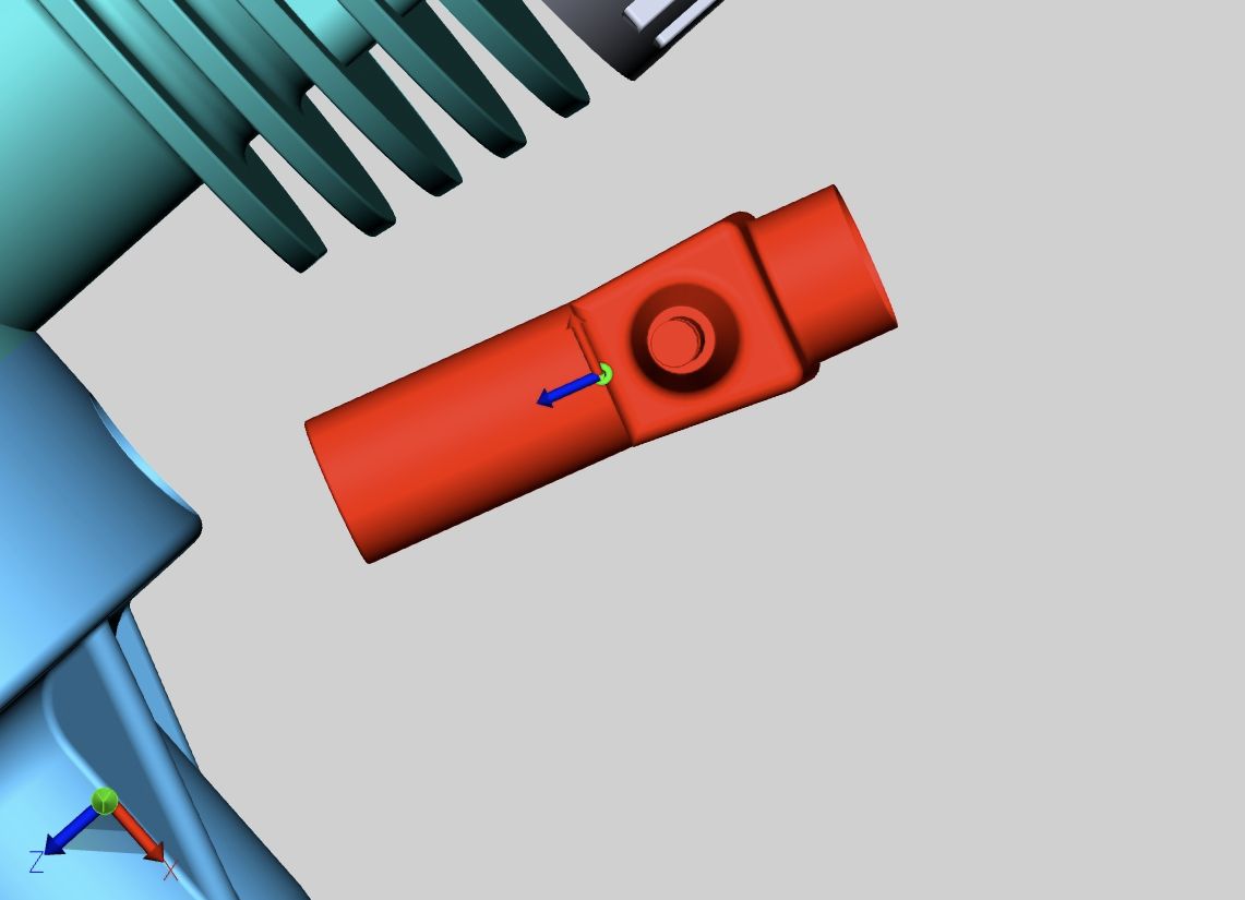
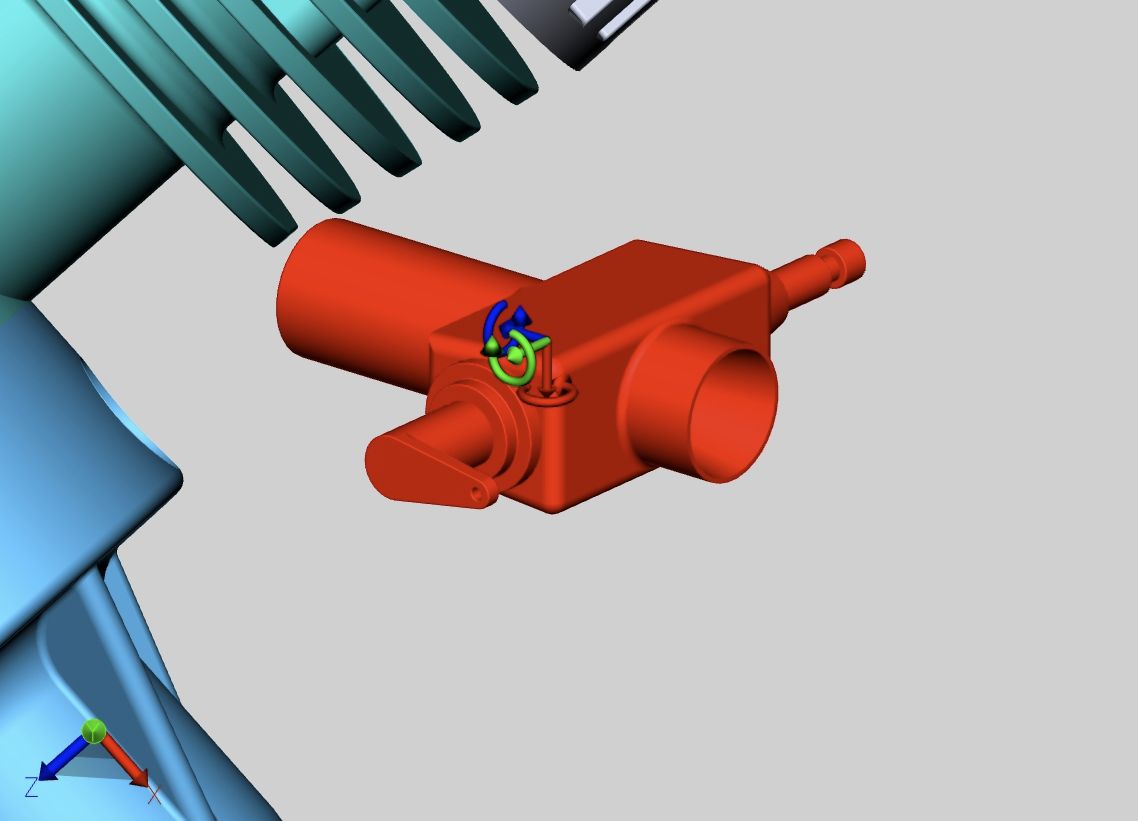
▪Click the handles and move the cursor to move or rotate objects directly in the model area. The Free drag function allows the repositioning of an object via drag & drop. The object is moved within the level currently selected as the model view.
▪Exit the transformation function by clicking the same button again within the function area or by pressing [ESC].
▪Clicking the [Reset position] button returns the object to its original position. Each individual transformation step can be reversed by clicking Undo in the Start ribbon.
Transformation by way of value entry
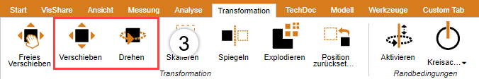
Initiate Free drag, Move or Rotate, as described in the section above. The tools pane appears, where the following options are provided for the exact change in position:
Transformation via the input of position coordinates
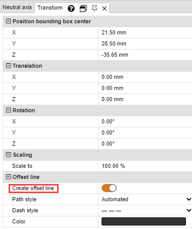
You will find the coordinates of your current selection under Position bounding box center. If you change the coordinates here, the selection is moved to the corresponding new position.
Transformation via the input of move values
A selection can also be moved in relation to the current position. This translation is the offset to the initial position. That means on the one hand that the selection will be reset to the initial position when the value [0] is entered, and on the other that various values can be tried out without having to compute previous entries. The values entered, as well as the initial position will remain intact until: the selection is deselected, a transformation is executed via the handles, or a value is entered under Rotation.
Entering rotation angle values
Just like for a translation, an angle value can be entered for Rotation to rotate the current selection on the relevant axis. The rotation axis passes through the bounding box center, unless boundary conditions were specified.
Create offset lines
Translations can be visualized via offset lines.
▪To do this, activate the Create offset line toggle in the tool area.
▪Adjust the line type, path type and color if necessary.
▪Use the Free drag or Move transformation function to move the desired objects out of the assembly.
▪Click the Delete offset lines button in the Tool Area to remove the created offset lines.
Boundary Conditions
Boundary conditions allow the limitation of transformations to specified axes. This function is particularly useful for transformations via reference points. Boundary conditions can be lines, e.g. at edges of geometries, circular axes or the axes of the coordinate system.
▪Choose a type for the boundary condition: Line, Circle Axis, X-Axis, Y-Axis or Z-Axis. In this example, the boundary condition circle axis is used.
Note: If you select one of the xyz axes as boundary condition, the corresponding xyz axis of the world coordinate system is used as boundary condition. However, if you use a custom coordinate system, the corresponding xyz axis of that coordinate system will be used. See chapter Generate Coordinate System
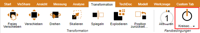
▪Move the cursor over a geometry. Possible positions for boundary conditions are highlighted.

▪Left-click a position to confirm.
▪The selected boundary condition is activated and is visualized in the 3D scene by an orange auxiliary geometry; additionally, the button [Boundary condition] axis is now highlighted.
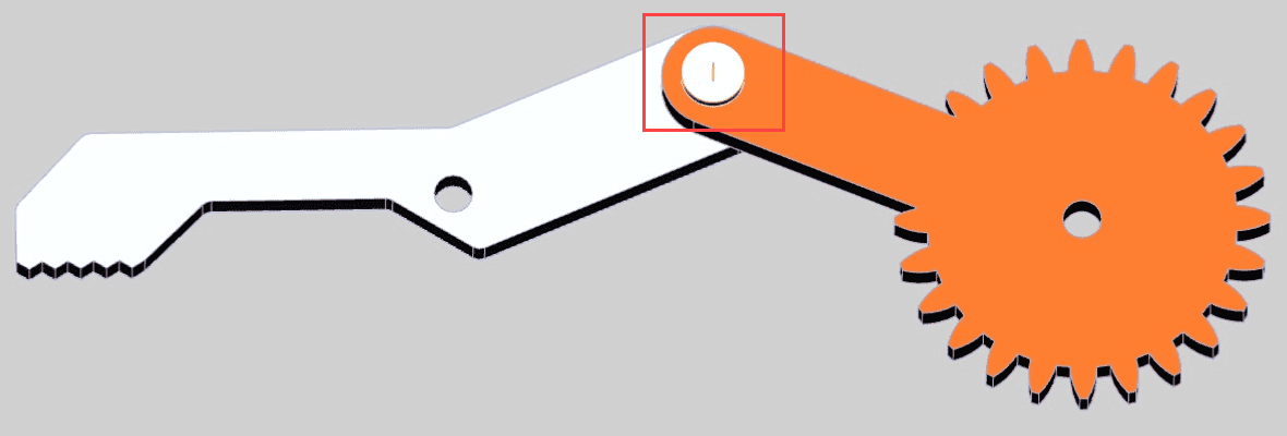
▪Select the desired transformation mode.
▪Select the object(s) you want to move or rotate around the boundary condition.
▪If now, as described above, a displacement or rotation is performed, this is only possible along the boundary condition just set.
Transformation via reference points
You have several options for transforming objects via reference points. These are divided into three categories for a better overview: Move, Rotate as well as Move and Rotate. Some of these transformations will require an active boundary condition (see above).

Move
This category contains only functions for moves without rotation.
Point to Point Translation
▪As a first step, select the parts you wish to move.
▪Select the Point to point function.
▪Select any starting point for the move. Lines, edges, corners, coordinate systems, etc. will be captured to place the exact initial position. Generally, you will first have to select a point on the selected object to achieve the expected transformation.
▪Select the end point for the move.
▪The selection will now be translated in such a way as to position the selected points congruently without any rotation.
Plane to Plane Translation
▪Choose a type for the boundary condition: Line or circle axis.
▪As a first step, select the parts you wish to move.
▪Select the Plane to plane function.
▪Select a plane on the part you want to translate.
▪Select the target plane for the move.
Rotate
This category contains only functions for rotations without translation.
Normal to Normal
This function allows you to align objects along the normal of areas, e.g. to position two areas in parallel.
▪As a first step, select the object you want to rotate.
▪Select the Normal to normal function.
▪Click the area for which you want to align the normal. Generally, you will first have to select an area on the selected object to achieve the expected transformation.
▪Now click the area to the normal of which you want to align the normal specified in point 3.
▪The selected areas will now be positioned in parallel.
Point to point
A boundary condition must be set first in order to use this transformation. You can then use this function to rotate objects based on two points around the axis defined by the boundary condition.
▪Specify a boundary condition as described above.
▪As a first step, select the parts you wish to move.
▪In the category Rotate, select the function Point to point.
▪Select any starting point of the rotation. Lines, edges, corners, coordinate systems, etc. will be captured to place the exact initial position. Generally, you will first have to select a point on the selected object to achieve the expected transformation.
▪Select the end point for the rotation.
▪The object is now rotated around the previously defined boundary condition so that the points are positioned as congruently as possible or at the least possible distance from each other.
Circle Center to Circle Center
A boundary condition must be set first in order to use this transformation. You can then use this function to rotate objects based on two circle centers around the axis defined by the boundary condition.
▪Specify a boundary condition as described above.
▪As a first step, select the parts you wish to move.
▪In the category Rotate, select the function Circle center to circle center.
▪Select any circle as starting point for the rotation. Generally, you will first have to select a circle on the selected object to achieve the expected transformation.
▪Select a circle as the end point of the rotation.
▪The object is now rotated around the previously defined boundary condition so that the circle centers are positioned as congruently as possible or at the least possible distance from each other.
Move and Rotate
This category contains functions that allow a move and rotation simultaneously.
Coordinate System to Coordinate System
You should familiarize yourself with the creation of coordinate systems before you use the function for the transformation from coordinate system to coordinate system.
▪As a first step, select the parts you wish to align. The initial coordinate system can be part of that selection.
▪Select the "Coordinate system to coordinate system" function.
▪Select the initial coordinate system for the translation in the 3D scene (usually part of the selection).
▪Select the target coordinate system for the translation in the 3D scene.
▪Your selection will be translated from the initial coordinate system to the target coordinate system in such a way that the two coordinate systems are congruent.
Circle Axis to Circle Axis
This function allows a positioning of your selection via circles.
1.As a first step, select the parts you wish to align.
2.Select the Circle axis to circle axis function.
3.Select any circle as starting point of the transformation. Generally, you will first have to select a circle on the selected object to achieve the expected transformation.
A successfully defined initial circle will be highlighted in orange. This circle will also contain a drawn coordinate system. Take note of the position of this coordinate system in relation to the circle axis for step 5.
4.Select another circle to which the previously selected circle is to be translated. Once the target circle is specified, it too will be highlighted in orange and it too will contain a drawn coordinate system.
5.You now have to specify the alignment to complete the transformation. Move the cursor to one or the other side of the target circle. The coordinate system preview on the circle axis will follow the cursor. Left-click to specify the alignment and complete the transformation.
6.The selection will now be transformed in such a way that the circles are positioned congruently, taking into account the orientation of the coordinate systems.
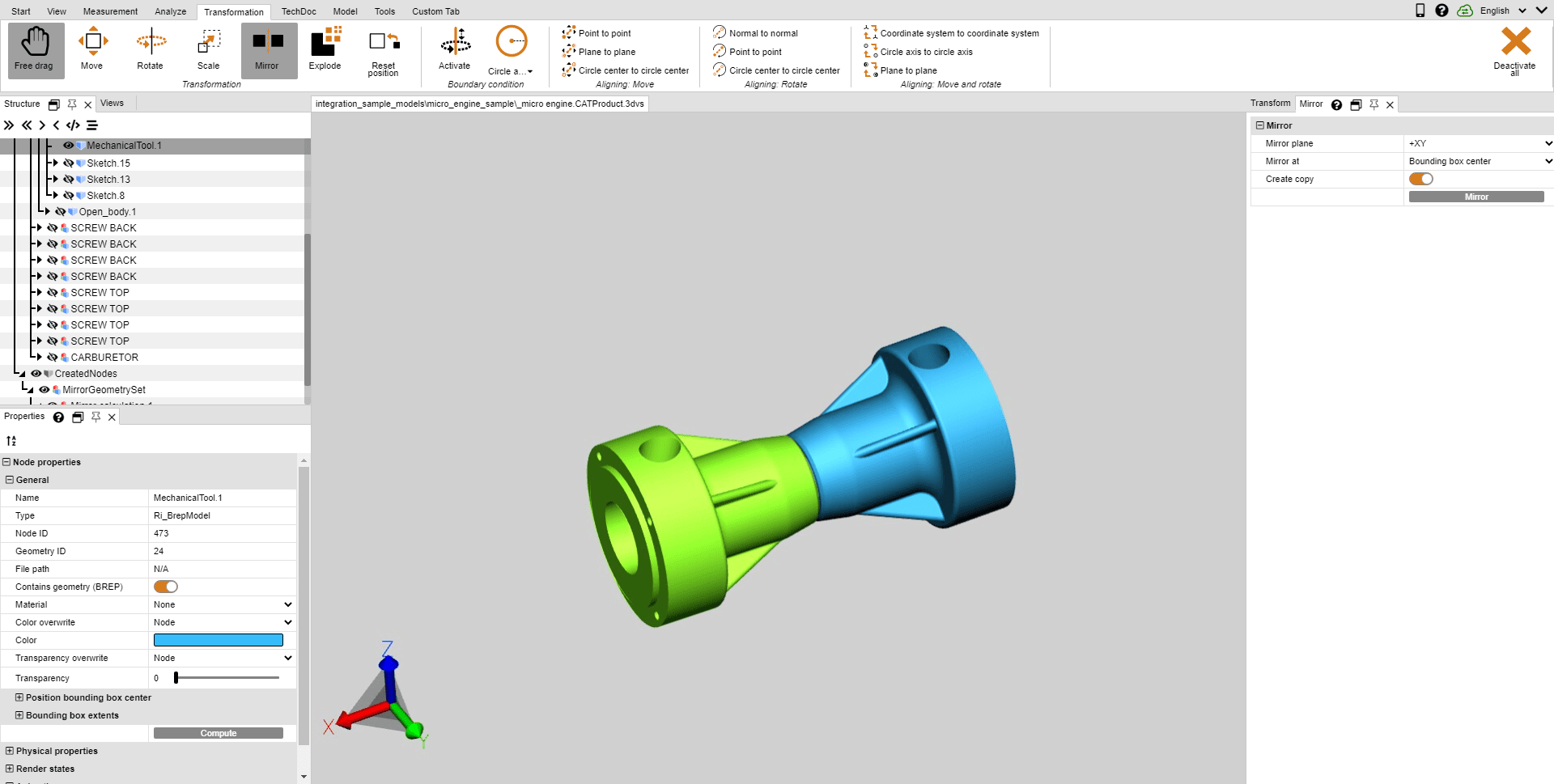
Reflection
1.Select the object to be mirrored.
2.Enable the Mirror function via the button in the Transformations tab.
3.Select the mirror plane in the tool pane menu.
4.Mark the checkbox Create copy to generate a new mirrored object instead of mirroring the original object. Objects created via the Mirror function will be saved under the structure node CreatedNodes/MirrorGeometrySet.
5.Click the Mirror button in the tool pane. In the illustration below, the object was subsequently moved.
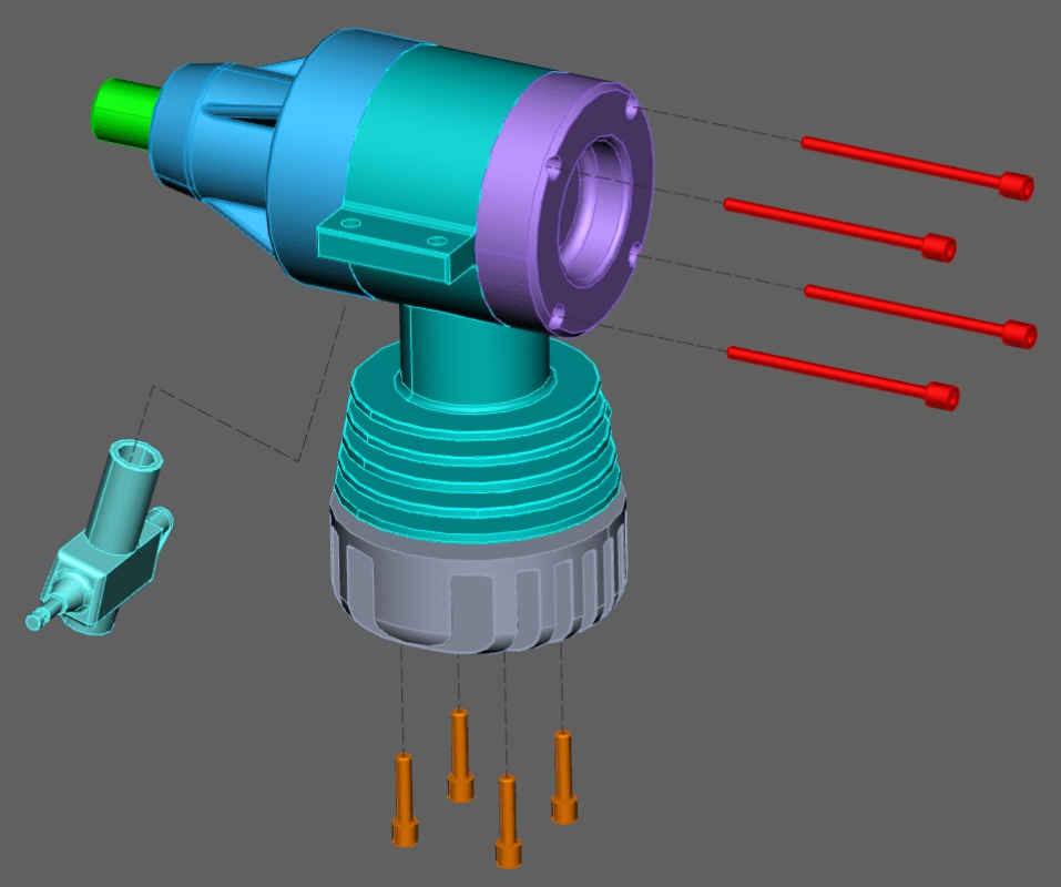
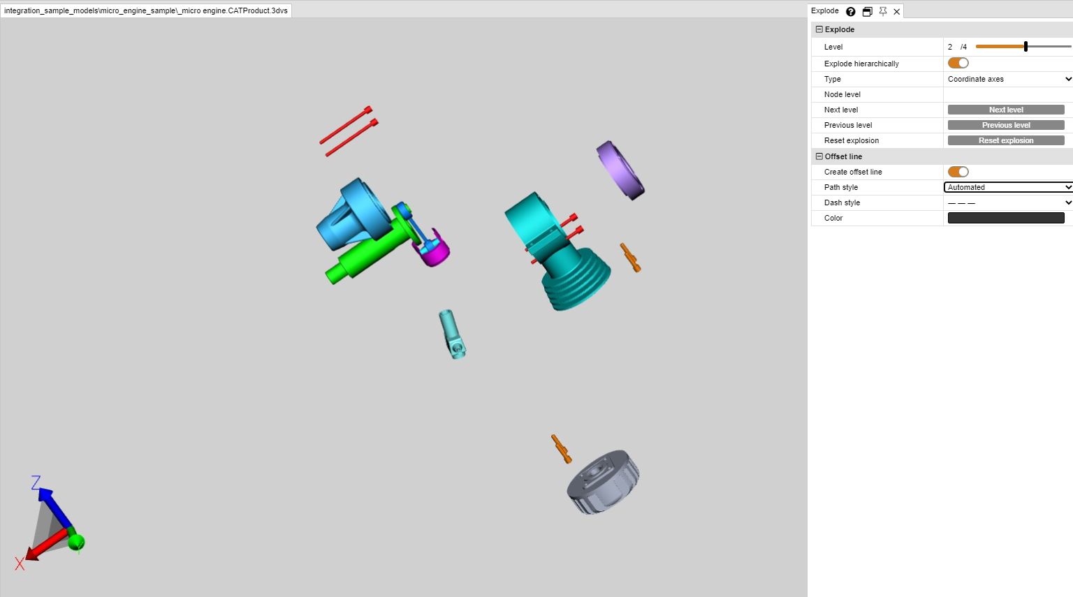
Explode
The function Explode allows you to move the individual parts of the model from the center to the outside. You can specify whether the hierarchy planes of the structure should be included.
1.Enable the Explode function via the button in the Transformations tab.
2.If you want to include the hierarchy planes of the structure when exploding, mark the Explode hierarchically option and activate, if necessary, the offset lines function.
3.Use the slider to set the desired explosion level or enter it manually. The result is displayed immediately.
Reset Position
Any transformed parts can be reset to their original position. Select one or more parts and click the button [Reset position].