


|
Navigation: Draft |
Scroll
 | |
|

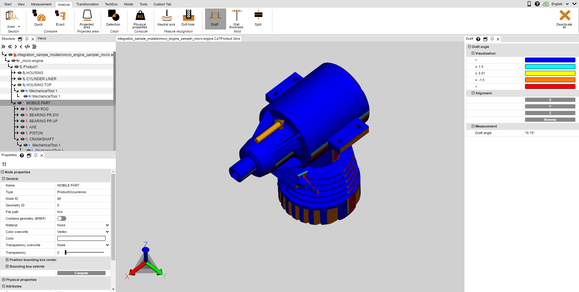
In the tab Analyze, you will find the tool Draft for the evaluation of possible demolding directions of a part or assembly. Depending on the specified direction, the entire visible model will be colored according to specification.
Proceed as follows to initiate a draft analysis:
▪Start the draft analysis; the cursor is displayed as an orange arrow.
▪Move the cursor over the model. The cursor will always be perpendicular to the area below. It will also follow line objects and coordinate system axes to verify specified directions in the model as needed.
▪Click the left mouse button at the desired positions to color the model in accordance with that draft direction.
▪The draft angles and their associated colors can be specified in the tool pane. Areas positioned at the specified angle to the draft direction will be colored accordingly.
▪The tool pane additionally offers the option to reverse the draft direction or to align it with the current coordinate system (chapter Generate Coordinate System).
▪The orange cursor for aligning the demolding direction can also be aligned with lines and coordinate systems.
▪Move the cursor over the model again to display the angle of the area perpendicular under the cursor in relation to the current draft direction in the tool pane under Draft.