

|
Navigation: Generate Coordinate System |
Scroll
 | |
|

3DViewStation allows you to generate and activate custom coordinate systems to use as reference for various functions (e.g. for Transformation).

You can use various methods for the generation of coordinate systems. Each option displays a preview of the coordinate system:
Circle center and planes: Select a circle into the center of which you want to place the coordinate origin. Next, click to select at least 2 planes perpendicular to each other. A preview of the coordinate system is displayed. Click the background to complete the creation. You didn't select enough planes if no preview is shown when you position the cursor on the background.
Circle axis: As a first step, select the desired circle and specify the alignment of the remaining axes with another click.
Right-Angled Planes: Select 3 planes perpendicular to each other. Clicking a previously selected plane again will invert the current axis.
Right-angled points: The first point denotes the origin, the second point the x axis and the third point the y and z axis. Lines and edges are captured to generate e.g. a coordinate system on the corners of rectangular solids.
Normal: Generates a coordinate system vertically on a plane.
Right-angled lines: With a method similar to Right-angled points, you can generate a coordinate system by selecting 2 consecutive lines at right angles to each other.
By line and point: In a first step, select a line specifying the z axis. You can then specify the remaining axes with another click (point).
Part bounding box: Generates a coordinate system at the center point of the part bounding box of a geometry. Activate the function first, and then select the part.
World: Generates a coordinate system at the center point of the part bounding box of a world.
Part: Generates a coordinate system at the origin of the selected part.
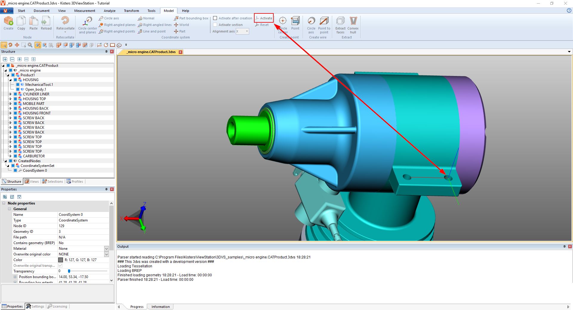
Activation of a coordinate system: A generated coordinate system must be activated to allow its use as reference for e.g. measurements. To activate a coordinate system, it must first be selected in the model area or in the structure, followed by an activation via the button Activate. An active coordinate system is displayed in color. The position of the coordinate system visualization in the bottom left corner of the model area is adjusted in accordance with the active coordinate system.
Click Reset to revert to the original world coordinate system.
You can automate the activation of a created coordinate system as follows:
▪In the info area, select the Settings tab.
▪Switch to the Active scenetab in the settings.
▪Navigate to Coordinate Systems > Action in the tree structure.
▪Select the Enable after generation check box.
The sub option of this setting allows the generation of a cut in the specified alignment axis for this coordinate system.